1. Preface
The ball pin is also called a ball head, a ball pin, a ball joint, and the like. The ball pin is an important part of the connecting part of the steering rod of the car, and is used for the articulation of the steering mechanism, such as the steering mechanism of the car and the articulation of the suspension.
Because the steering wheel of the car has a camber angle and a toe angle, the kingpin has a back rake angle and a camber angle, so the steering rod generally moves in space during steering and when the wheel is bouncing up and down.
For this purpose, ball joints are applied at the joints of the transmission. The ball pin needs to be wear-resistant and the core can withstand certain strength and toughness. The ball pin assembly generally comprises a ball pin, a ball seat, a ball bowl, a cover and a sealing cover.
The ball pin assembly is connected with the control arm and the steering knuckle. It needs to transmit force and torque to ensure the normal operation of the vehicle. Therefore, each joint must be rigidly connected to ensure the strength and rigidity requirements. At the same time, each component must not be Slip, deformation, or damage.
There are five main ways to connect the ball pin to the control arm, namely, riveted type, bolted type, pressed-in type, welded type, integrated type and the like.
The one-piece connection integrates the ball head and the control arm, which has better strength and smaller space, but the cost is high. It is generally used in the middle and high-grade suspension, and the other four are common ways. Factors such as design space, process and cost should be considered together to determine the appropriate form of connection.
There are three main ways to connect the ball pin to the steering knuckle, namely a taper connection, a slotted cylindrical connection, and a cylindrical connection with a spherical surface. Among them, the cylindrical connection with spherical surface is used for the knuckle of aluminum alloy, the main purpose is to increase the contact area and prevent the buckling deformation of the aluminum alloy.
The taper connection (Fig. 1) and the slotted cylinder (Fig. 2) are mainly used for the knuckle of cast iron. This paper mainly introduces the design calculation of the ball pin and the steering knuckle using the taper connection and the slotted cylinder connection.

Figure 1 Taper connection

Figure 2 Slotted cylindrical connection
2. Design calculation of ball pin
The ball pin working surface should be well lubricated, so there are oil grooves or oil passages on the ball bowl or ball pin. However, in order to reduce the maintenance work, the current ball pin generally adopts a plastic ball bowl which does not need to be filled with lubricating oil, that is, the self-lubricating ball bowl, which is widely used in the design of modern automobile ball pin. application.
Although the shape of the ball pin is complicated, the diameter of each part is generally proportional to the diameter of the ball pin, so that the ball pin of the standard model can be dimensioned.
The diameter of the ball head is generally related to the ball pin load. It needs special attention when marking the mark. It can be selected according to the recommended range of Table 1. The diameter of the ball head is the common size of domestic cars, and the diameter of the current car head design will be There is a difference in the diameter of the ball head. For example, in the Volkswagen and General Motors, the diameter of the ball head of Φ26 mm not included in the table is often used.

The diameter of the ball pin in the car is divided into Φ24mm, Φ26mm, Φ28mm, Φ30mm, Φ32mm and Φ35mm. The ball factory specializes in the diameter and size series according to the actual situation.
Generally, the larger the diameter of the ball pin, the higher the load carrying capacity; in the case of the same size as the knuckle connection, the larger the diameter, the larger the swing angle that can be achieved. Normally, the ball pin diameter is determined by the ball bearing capacity and swing angle requirements.
For the design of the car ball pin, the general ball diameter Φ24mm is suitable for the mini-car; the diameter Φ26mm is suitable for the A-class or A0-class sedan; the diameter Φ28mm is more suitable for the B-class sedan or the urban SUV; the diameter Φ30mm is more suitable for the C-class sedan or Urban SUV; diameter Φ32mm and Φ35mm are suitable for large-load vehicles such as C-class sedan, SUV, MPV and pickup truck. See Table 2 for the selection of the ball-type ball diameter of the standard model.

The ball pin can be made of carburized steel 12CrNi3, 15CrMo, 20CrNi, 20CrMnTi, cyanide steel 35Cr, 35CrNi, quenched and tempered steel SCM435 and other materials.
In order to meet the wear resistance requirements, it is usually necessary to do surface treatment such as carburizing and quenching, carbonitriding, surface induction quenching, etc. The specific requirements can refer to the NY/T1122 wheeled tractor steering ball pin, GB/T7726 articulated bus mechanical connecting device Designed by standard, it can also be referred to the ball pin design requirements of more mature models, such as the surface treatment requirements for carbonitriding (example is shown in Figure 3). Surface treatment requirements for surface induction hardening (example is shown in Figure 4).

Figure 3 Example of carbonitriding surface treatment requirements

Figure 4 Example of induction hardening surface treatment requirements
For the ball pin, it is generally necessary to check the minimum cross section (diameter Db) of the ball pin, the stress of the ball pin and the knuckle mounting end face (diameter Dc), and at the same time, it is necessary to check the unit pressure of the spherical surface (ie, the wear resistance of the check spherical surface) Sex).
According to the load file of the hard point of the ball pin, find the load in the x, y, and x directions under the maximum fatigue load condition and the maximum limit load condition, and transform the load in the x, y, and z directions into Figure 5. The load shown, and calculate the maximum bending stress and the combined stress σ1 and σ2 of the maximum bending stress and tensile stress at the ball pin and the knuckle mounting end face according to the relevant size of the ball pin;
The stress of the two should be less than the yield strength of the ball pin material under the maximum fatigue load condition. Under the maximum limit condition, the yield strength of the material can be exceeded. Here, the CAE calculation analysis is needed to calculate the area of ​​the stress exceeding the yield strength. to evaluate;
Because the bending stress is linear, the surface bending stress generally exceeds the yield strength, and the bending stress below the surface is far less than the yield strength. The ball can still continue to withstand a certain load (Figure 6), and finally verified by the bending test. According to experience, it is generally recommended that the minimum yield strength of the ball test is 120% of the lower strength of the maximum load.

Figure 5 Schematic diagram of the force of the ball pin

Figure 6 Schematic diagram of ball pin CAE analysis
The stress at the smallest section of the ball pin (diameter Db) is:

In the formula:
Σ1 is the normal stress at the smallest section of the ball pin;
b is the radial force FR to the minimum cross-sectional dimension of the ball pin (force arm);
Db is the diameter of the smallest section of the ball pin;
FR is the radial force of the ball pin under the maximum load condition (generally the combined force in the plane of the smallest section, such as the combined force in the x and y directions);
Fa is the axial force under the maximum load condition of the ball pin.
The stress at the ball pin and the knuckle mounting end face (diameter Dc) is:

In the formula:
Σ2 is the normal stress at the mounting end of the ball pin and the steering knuckle;
c is the radial force FR to the size of the ball pin and the knuckle mounting end face (force arm);
Dc is the diameter of the ball pin and the knuckle mounting end face;
The unit stress (pressure) at the ball bearing spherical surface is:

In the formula:
P is the unit stress carrying the spherical portion;
F is the resultant force acting on the center of the ball;
A is the projected area of ​​the ball bearing surface in a plane perpendicular to the resultant force F direction.
After calculation, the unit stress at the ball bearing spherical surface is generally required to be ≤25MPa~35MPa, and the ball diameter of the ball pin can be determined by the result.
The American standard has relevant standards for ball pins, as shown in Figure 7, which can be referenced during design, including the tightening torque requirements of the nut.

Figure 7 Schematic diagram of the design of the ball in the American standard
The standard tightening nut is mainly a hexagonal slotted self-locking nut. If a hexagonal flange nut is used in design, the tightening torque should be slightly larger than the standard, and finally determined according to the actual design requirements. See Table 3 for the relevant dimensions and torque requirements of the American standard. .
Table 3 American standard ball pin size and torque requirements

3. Design analysis of steering knuckle
3.1 Analysis of steering joint design with tapered connection
The knuckle design calculation of the tapered connection method is mainly to design the ball pin mounting hole diameter and the knuckle thickness at the connection between the ball pin and the steering knuckle. It is mainly checked according to the calculation method of the interference fit, and finally the knuckle is checked to meet the strength requirement after the ball pin is tightened.
In mechanical design, the strength of the interference joint includes two aspects, namely the strength of the joint and the strength of the joint itself. The compressive strength limit of the containment member in the general interference connection and the tensile strength limit of the containment member are checked against the yield limit or tensile limit of the material.
However, in the design of the interference connection between the ball pin and the steering knuckle, the method is used for checking, and the pulling amount is often not satisfactory. Therefore, according to practical experience, the design of the interference connection between the ball pin and the steering knuckle is calculated according to the compressive strength (support strength) of the material. There is no relevant data in the general material manual of the compressive strength, and the hardness can be calculated. The method is converted.
3.2 Analysis of steering knuckle design with slotted cylindrical connection
There is no interference contact between the knuckle of the slotted cylindrical connection and the ball pin. Therefore, there is no initial compressive stress between the joint faces. Therefore, there is a certain connection between the calculation method and the requirement of the type of the cone. Difference, this type of steering knuckle mainly calculates the compressive stress under the working load and the compressive stress (supporting stress) when the knuckle yields, and compares the relationship between the two.
The size of the ball pin and the steering knuckle of the slotted cylinder connection is shown in Fig. 8. Under the action of the working load F, the ball pin still has the same pressure and bending moment as the conical connection. It is necessary to calculate the knuckle of the two stress superimposed states. The maximum compressive stress experienced.

Figure 8 Slotted cylindrical connection method ball pin and steering knuckle size diagram
The calculation of the ball pin itself by the formula is very complicated. It is recommended to use the finite element method for analysis, and good results can be obtained. Finally, the actual tightening test can be carried out through the sample to determine the appropriate tightening torque.
Taking the steering knuckle of a certain model and the steering ball pin connection as an example (Fig. 9), the tightening torque and the pull-in amount tested are shown in Table 4.

Figure 9 knuckle and steering rod ball pin
Table 4 Tightening torque of knuckle and steering rod ball pin at 35Nm+90°
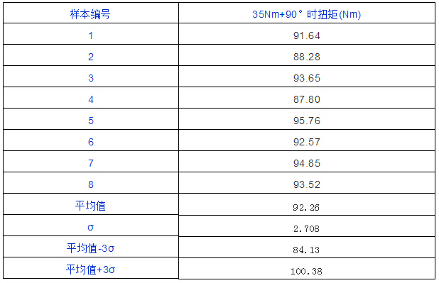
The tightening torque set by this model is 35Nm+90°. It can be seen from the test data that the final tightening torque is about 90Nm, and the amount of pull-in is slightly different when the ball pin is in the lubrication and non-lubrication state. The tightening torque is only about 60 Nm when not lubricated (Table 5).
Table 5 Tightening torque of knuckle and steering rod ball pin at 35Nm+90° (when lubricated)

4 Conclusion
The selection of the ball pin should be calculated and selected based on the actual load.
Regardless of the type of knuckle and ball pin connection, the compressive stress that the knuckle bore can withstand determines whether the design requirements are met.
In the case of the same amount of pull-in, lubrication and non-lubrication have a large difference in the final tightening torque.
DIY tool cabinets are super hot online and they have mail order packings for safety in delivery.
Diy Tool Chest,Diy Tool Cabinets,Diy Mobile Tool Cabinet,Diy Tool Storage Cabinet
Changzhou Xingsheng Tianhe Electric Appliance Co., Ltd , https://www.roller-tool-cabinet.com