MasterCAM is a CAD/CAM CNC system developed by CNC Software of the United States, focusing on CNC machining. When using MasterCAM for NC machining, the NCI file is first generated based on the graphic information and the machining information, but the NCI file cannot be directly transmitted to the CNC machine tool. It is also necessary to convert the NCI file into a CNC system through the post processing program dedicated to each CNC system. And the recognized NC file can control the normal operation of the CNC machine.
MasterCAM comes with a lot of post-processing programs, but it is mainly developed according to the Japanese FANUC controller. The XH716A vertical machining center of our school adopts SINUMERIK802D numerical control system. The corresponding post-processing program can not be found in MasterCAM. It must be based on the structure of CNC machine tool, the programming principle of control system and the requirements of communication interface. The post-processing program, MPFAN makes the necessary modifications and resets to meet the needs of CNC machining.
First, the part that needs to be modified
1. Modify the code with the same function and inconsistent symbols
Modify "Srad"R"" in "#Address string definitions" to "Srad"CR"", "Srminus"R-"" to "Srminus"CR=-""; "#Select English/Metric "Sg20 G20" in Code" is changed to "Sg20 G70", "Sg21 G21" is changed to "Sg21 G71"; "Sg28 G28" in "#Select reference return code" is modified to "Sg28 G74"; "Fmt P11 Dwell is changed to "Fmt F 11 Dwell" in #Toolchange/NC Output Variable Formats"; ""M01"" in "#Start of File and Toolchange Setup" is changed to ""M0"", " Change "M30" to "M2".
2. Program start, end and modification of automatic tool change format
The changes in this section are made in "#Start of File and Toolchange Setup".
(1) Change the file header ""%", E" to ""%_N_", Progname, "_MPF", E".
(2) "*Progno,e", ""(PROGRAM NAME-",Sprogname,")",e","" (DATE=DD-MM-YY-",Date," which will not be recognized in 802D TIME=HH:MM-",Time,")",e","Ptoolcomment", "Pbld,N,"G43",*Tlngno,Pfzout,Scoolant,Next_Tool,e","Pfbld,N,"G92" , *xh, *yh, *zh, E" and the second ""%", e" preceded by the "#", (beginning with the "#" sign as an annotation, does not affect program execution).
(3) Modify the output format of the first block "Pbld, n, *Sgcode, *Sgplane, "G40", "G49", "G80", *Sgabsinc, e" to "Pbld, N, *Sgabsinc," G54", "G64", E". The machining plane XY is the default setting for 802D and Mastercam, so it is not listed in the modified output format.
(4) 802D operation programming requires that the tool change command "M6" must occupy a single block, so "Pbld, N, *T, "M6", e" should be written as "Pbld, N, *T" in two lines. , "N, "M6", e", that is, the output occupies two blocks.
(5) Delete the reset item *Sgabsinc and reset the items in "Pcan1, Pbld, N, *Sgcode, *Sgabsinc, Pwcs, Pfxout, Pfyout, Pfcout, *Speed, *Spindle, Pgear, Strcantext, e" *Sgabsinc" deleted.
(6) In China, the metric unit is generally the default setting of 802D and Mastercam. If you do the same, you can add “#†in front of “Pbld, n, *Smetric, eâ€.
Second, the reset part
1. Setting of the axis
The XH716A vertical machining center is a three-axis linkage. Without the rotary axis, find the rotary axis setting section "#Rotary Axis Settings", change "Rot_On_X:1" to "Rot_On_X:0" or find "#Numbered questions for Mastercam Mill". To answer the question, change "164.Enable Rotary Axis Button?Y" to "164.Enable Rotary Axis Button?N" to close the fourth axis.
2. Setting of circular interpolation mode
The Mpfan post-processing program can be set up with three circular interpolation methods, and the SINUMERIK 802D numerical control system supports all three circular interpolation methods. (1) Maintain "Arcoutput:1" in "#General Output Settings" or set to "Arcoutput:2". The latter must also change "Srad"R" in "#Address String Definitions" to "Srad"Cr"", "Srminus"R-"" to "Srminus"Cr=-"" because of the output The radius is involved in the NC program. (2) Set "Arcoutput:1" in "#General Output Settings" to "Arcoutput:0".
3. Hole processing fixed cycle switch settings
Since the instruction code and output format of the hole processing fixed cycle of the 802D system are completely different from those of the MPFAN post-processing program, the best way to handle is to turn off the enable switches in "#Enable Canned Drill Cycle Switches", that is, "Usecandrill" : No", "Usecanpeck: No", "Usecanchip: No", "Usecantap: No", "Usecanbore1: No", "Usecanbore2: No", "Usecanmisc1: No", "Usecanmisc2: No". Thus, when the hole machining is performed using the MasterCAM hole machining menu, a hole machining fixed cycle program composed of "G0", "G1", "G4", and the retention time "F" is generated.
4. Communication interface parameter settings
It can be set according to the interface parameters of 802D and the actual wiring condition of the computer. The specific settings are as follows:
80.Communications port number for receive and transmit (1 or 2) ? 1;
81. Data rate (110, 150, 300, 600, 1200, 2400, 4800, 9600, 14400, 19200, 38400)? 19200;
82. Parity (E/O/N)? N;
83. Data bits (7 or 8)? 8;
84. Stop bits (1 or 2)? 1;
85. Strip line feeds? N;
86. Delay after end of line (seconds)? 0;
87. Ascii, Eia, or Binary (A/E/B)? A;
88. Echo keyboard to screen in terminal emulation? N;
89. Strip carriage returns? Nâ€.
Third, processing examples
1. 2D shape milling
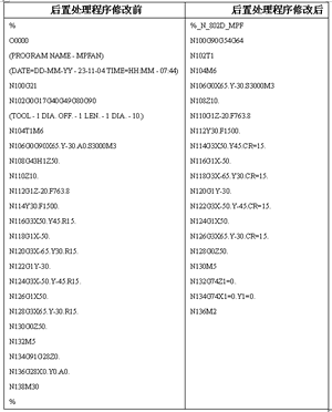
If you select the "Toolpaths - Contour" command under the main menu to perform 2D shape milling on the periphery of the part shown in Figure 1, use the post-modification post-processing program "MPFAN" and the modified post-processing program "802D". The generated machining program is shown in Table 1.

Figure 1 parts drawing
Table 1 The shape milling program generated before and after the modification and setting of the post-processor

2. Drilling
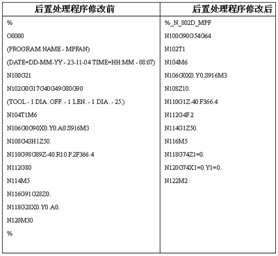
If you select the "Toolpaths - Drill" command under the main menu, the circle in the machined part is drilled, and the second tab of the drilling process is set as shown in Figure 2. The machining program generated by the post-modification post-processing program "MPFAN" and the modified post-processing program "802D" is as shown in Table 2.

Figure 2 Settings for the second tab of the drilling process
Table 2 Drilling program generated before and after modification and setting of post-processor

Bathroom Faucet,Basin Faucet Bathroom,Bathroom Mixer Tap,Wall Mount Mixer Tap
kaiping aida sanitary ware technology co.,ltd , https://www.faucetkpaida.com