SDY-GB high and low voltage CT ratio tester using method:
Test preparation:
1. Check the appearance of each part of the instrument and proceed to the next step without damage, deformation, contamination, or water damage.
2. Turn on the power switch and observe the voltage value and remaining battery percentage of each part of the LCD screen to see if the battery power is enough.
3. Check whether the operation of the insulation rod is normal, whether the function of the locking part of each rod is normal, whether it can be locked and relaxed flexibly, and can be used after being normal.
High-low pressure CT ratio tester test procedure:
1. Connect the low-voltage clamp meter to the host, pay attention to the interface to lock, prevent open circuit;
2. Connect the host antenna to ensure the quality of wireless communication is good (if the distance between the high and low voltage measured points is very close, and there is no obstacle, you do not need to connect the antenna);
3, open the host power, select to enter the "change ratio measurement" function screen;
4. Place the low voltage clamp on one of the secondary conductors of the transformer under test, so that the current flows in from the direction of the inflow end of the clamp meter. Also note that the jaws are well closed; this time, the LCD screen of the host computer should be available. Shows the magnitude of the secondary current;
4. Connect the high-voltage clamp meter with the insulation rod, adjust the length of the insulation rod according to the height of the tested circuit, and ensure that the connection of each rod is really tight;
5. Push the insulation rod upwards and place the high-voltage clamp on the primary conductor of the transformer to be measured. Also pay attention to the inflow direction of the current and the good closing of the jaws.
6, read the host test results;
7. Pull down the insulation rod to make the high-voltage clamp meter and the circuit under test disconnected. The action should be gentle, and do not pull it violently to prevent the mechanical structure from being damaged.
8, put away the insulation rod, close the power of the high-voltage clamp meter, and remove it from the insulation rod;
9, take off the low voltage clamp meter from the second line, and then remove the low voltage clamp meter from the host;
9, turn off the host power supply, take off the antenna;
10, all accessories received in the box, the test is completed.
The liquid crystal display interface mainly has three screens, including a main menu and three function interfaces, which are described in detail below.
1. The boot interface is shown in Figure 3:
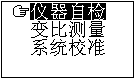
The figure shows that there are three options in the main menu: Instrument Self-Test, Ratio Measurement, and System Calibration. When the cursor points to which function option, which icon becomes reversed white, it can be seen that the selected item in the interface of Fig. 3 is the 'instrument self-test' function. Press the up, down, left, and right keys to change the options pointed by the cursor. At this point, press 'OK' to enter the selected function display. The system calibration is a calibration interface for the manufacturer before leaving the factory, and the user does not need to understand.
Sixth, high and low voltage CT ratio tester charging instructions
Both the instrument host and the wireless high-voltage clamp meter are equipped with a high-performance lithium-polymer rechargeable battery. The host computer and the wireless high-voltage clamp meter can display the current voltage and the remaining power of the internal battery in the host liquid crystal interface. The front of the wireless high-voltage clamp meter is also displayed. Three power indicator lights are set to represent the remaining power of 30% (one light), 60% (two lights), and 90% (three lights);
When the remaining battery power is less than 10%, the instrument should be charged in time. Otherwise, it may affect normal use.
Generally, the charging time can be more than 6 hours, and after it is fully charged, it will automatically change to the floating state and will not cause damage to the battery due to prolonged charging.
The host and the high-voltage clamp meter share the same charger and can charge two parts at the same time; pay attention to the connection of the charger and the instrument before charging, and then connect the power cord of the charger to the AC 220V power supply. Do not confuse the order, otherwise it may cause the charger to protect and cannot be charged.
This kind of battery has no memory effect. To prevent the battery from being used, it can be charged at any time.
We are proud to introduce our coverall, it has many features that set it apart, such as cargo pockets, reflective strip on pockets and zipper access to your trousers pockets, all little extra details make Safety Coverall to be a truly functional and practical offering, perfect for wearing on the roads, near the trackside or mechanics engineering fixing.
Safety Coverall
Safety Coverall,Fire Retardant Coveralls,Flame Resistant Coveralls,Fire Resistant Coveralls
Xinxiang Zhongke Reflective Material Co., Ltd. , https://www.safetyvest.pl