When the monitoring center does not receive the image, the engineer first checks whether the camera ball or the ball machine is normal. When testing the camera equipment, the engineer uses the video surveillance integrated test instrument to do three aspects of testing: First, use the meter to test whether the camera has an image, and the 3.5-inch color display of the meter can clearly display the image captured by the camera. The image or the received image is abnormal, indicating that the camera is faulty. Second, the video signal attenuation measurement of the monitoring integrated tester is used to measure the video re-level of the camera. The normal range is 800-1000 mV. If the level is too low, the image will be changed. Dark, the level is too high will cause virtual shadow; Third, use the meter's multimeter to measure whether the transformer's transformer power supply is normal, the general transformer output is DC 12V, the ball machine's transformer output is AC 24V, the transformer is the monitoring system failure rate comparison High accessories.
PTZ control maintenance
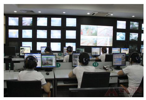
In the security monitoring system, the pan/tilt or ball machine is widely used, and the monitoring center staff can maneuver the camera angle. When the pan/tilt or the ball machine is not controlled, or can not rotate at a certain position, the engineer needs to carry the multifunction. The keyboard tests whether the pan/tilt or the dome is rotating normally. However, different PTZ or dome manufacturers have their own proprietary protocols. When the engineer maintains the dome, it must bring the corresponding multi-function keyboard test. It is possible to have multiple keyboards for testing different domes. The engineers used the video surveillance integrated tester to solve this problem well, because it embedded more than 30 kinds of protocols such as Pelco-D/P and BOSCH, and the PTZ reversal test function dedicated to testing the rotation of the gimbal. The personnel can operate the gimbal through the instrument to keep turning, and observe whether there is a card position when the gimbal rotates.
Video optical end maintenance
The video optical transceiver is divided into a transmitting end device and a receiving end device, and the transmitting end device is placed outside the camera like a camera, and the engineering personnel usually perform a maintenance test on the transmitting end device. For the maintenance work of the optical transceiver, the test is carried out in three steps. First, use the multimeter of the video surveillance integrated tester to measure whether the power supply of the optical transceiver is normal. Generally, the power input is DC 5V. Secondly, whether the optical output power of the optical transceiver is normal, the transmitting wavelength of the transmitting end is 1310n, the receiving wavelength is 1510n, and the optical transceiver of 20KM. The general transmit power is about -9dBm. Third, it is normal to test the video port of the optical transceiver and RS485/RS232 communication. The monitoring integrated tester sends the standard color pattern image signal to the video optical transceiver. The monitoring center receives the test color strip sent by the video optical transceiver, indicating that the video transmission part is normal; and the RS485/RS232 data capture function of the instrument receives the control signal of the optical transceiver. If the control code sent from the monitoring center is received, the RS485/RS232 communication transmission of the optical transceiver is normal.
BNC coaxial cable transmission maintenance
In the current video surveillance system, traditional analog images dominate, and IP digital cameras are gaining popularity in the future due to compatibility issues. Generally, small-area monitoring systems such as factories and buildings directly use BNC coaxial cables to transmit images. BNC coaxial cables are weak in anti-interference, and each BNC cable can only transmit one video. However, because the monitoring area is small, the same Axis cable transmission is relatively low cost, and BNC coaxial cable is commonly used. The BNC cable is degraded or even interrupted due to aging and man-made damage. In the maintenance work, it is usually necessary to check whether the BNC cable has a problem.
When the engineer maintains the cable, use the integrated tester to do the three-step work. First, at the camera end, connect the BNC cable to the meter, and use the image generator of the meter to send the standard color pattern bar. Under normal circumstances. The monitor of the monitoring center should receive the same color pattern bar. This step determines whether the BNC line is disconnected, and the monitoring center receives the image color is normal. Second, in the monitoring center, the meter's video signal attenuation measurement function is used. Whether the measurement video re-level is attenuated after being transmitted through the BNC cable is generally too large, generally 800-1000 mV, and the attenuation is too large, causing image jitter and image darkening. Third, if the BNC cable is disconnected in the middle, because the BNC cable is buried in the line slot, it is very difficult for the engineer to find the fault point without the test tool. Using the line test function of the integrated test instrument, the meter emits a signal and measures the fault. Point location, for the engineering staff to find the location of the breakpoint immediately, greatly improving work efficiency.
Fiber transmission maintenance
Optical fiber transmission has the characteristics of large capacity, high speed, high stability, etc. Video surveillance systems are increasingly using optical fiber devices such as video optical transceivers and optical transceivers to transmit video images and control signals. Large-scale monitoring systems such as highway monitoring and safe city monitoring use optical fiber transmission to achieve high-stable video transmission. With the development of optical fiber communication technology, the price of video optical terminals and optical fiber cables is getting lower and lower, and video surveillance systems use optical fibers. Transmission has become very popular. Optical fiber transmission is usually used for signal transmission between several hundred meters and one hundred kilometers. It is also an indispensable part to detect fiber optic cables. For fiber maintenance, engineers must use professional fiber optic test instruments such as light sources, optical power meters, OTDRs, and more. The stable light source is specially used to emit laser light with high stable power value. The laser light has a certain attenuation after being transmitted through the optical fiber. The power value transmitted through the optical fiber is measured by the optical power meter, and the fiber loss value is calculated as dB. Measuring fiber consumption time must be paired with a light source and an optical power meter to prepare for calculation of fiber loss; and OTDR is an instrument used to measure the breakpoint position of the fiber. It detects how many kilometers the fiber is disconnected, but the cost of the OTDR. Too high, smaller engineers can use fiber optic obstacle finder to measure breakpoint locations. For small-scale engineers, the most needed fiber optic measurement tool is the optical power meter. Because long-distance fiber optic cables are usually maintained by telecom operators or radio and television systems, small-scale engineers only need to measure the power and fiber loss of fiber optic equipment. Finding the problem is enough.
Machine to produce the outside earloop & inside earloop face mask. The proced is from spunlace fabric material feeding, elastic earloop welding & nose wire welding to finished product. None operator, and can be used in Medial face mask machine, Dust-free mask etc.
Including function:Non Woven Mask Making
Machine size
6700*3200*1680mm
Yield
100pcs/min
Machine weight
1600KG
Voltage
220V
Power
11KW
Pressure
6kg/cm²
Fuselage material
Aluminium alloy
Control mode
PLC
Detection mode
Photoelectric detection
Remarks
A machine can produce a variety of common mask
Feature
1.Multifunction and Higher Efficiency,lower trouble.
2.Stainless steel structure,independent electrical control box.
3.The parts surface adopts chorme dealing,covering parts of stainless steel,looking beautiful and clean.
4.Machine with Multifunction,and change the model for each different size shoes cover producing.
5.Automatic piece Account, Machine with Stop Protection.
Face Mask Machine
face mask machine, kn95 mask machine, 3ply mask machine
Dongguan Bangwei Labor Insurance Supplies Co., Ltd , https://www.bangweimedical.com